The full notch creep test according to ISO 16770 is rapidly becoming the preferred way of measuring the stress crack resistance of a polyethylene.
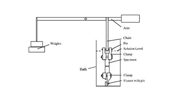
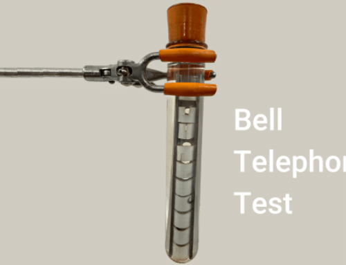
The diagrams above show how the full notch creep test involves a square bar of material, which is notched on all four faces in coplanar fashion. A constant stress is applied to the specimen, most conveniently via a lever arm loading arrangement, and the time for the specimen to fail is recorded. The specimens are generally tested at elevated temperature in a test fluid, which is often a detergent solution to accelerate cracking. The stress level applied to the specimen depends upon the stress crack resistance of the material and the test temperature.


The aim of this test is to assess resistance to brittle failure and the schematic diagram above shows the fracture surface that is sought. In order to achieve brittle failure at any given temperature, the applied stress levels must be significantly lower than the corresponding yield stress at that temperature.
ISO 16770 – Full Notch Creep Test Part 2 – Further Detail
 The graph shows typical data plotted as applied ligament stress (i.e. stress calculated as applied load divided by the remaining area after notching) versus the failure time. At high stresses, failure occurs quickly and is ductile. At lower stresses, the failure is brittle and takes much longer to occur. It is the brittle data (red points) which characterizes the stress crack resistance of the material. Rather than measure data at many different stress levels, it is possible to specify set conditions for different polyethylene applications and perform a limited number of full notch creep tests at those conditions in order to define the performance.
For example, the typical conditions for PE pipe grades, during a full notch creep test are:
- 80°C
- 2% Arkopal N110 (nonylphenoxy poly(ethyleneoxy)ethanol)
- 6MPa
ISO 16770 – Full Notch Creep Test Part 3 – Further Practical Issues
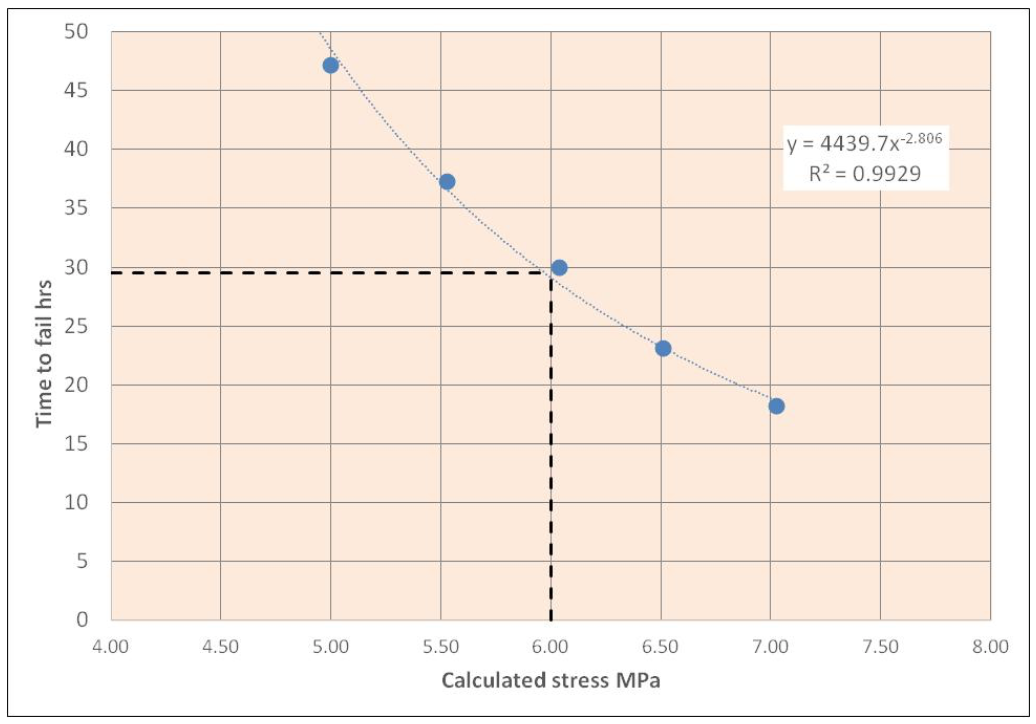
A practical problem with a Full Notch Creep Test is achieving the correct test stress level because of difficulties in guaranteeing the exact ligament dimensions. Rather than perform multiple tests at one stress level, it is preferable to test at several stress levels close to the required reference stress.

For example, the above graph shows data for a blow moulding grades where the typical test conditions are 50°C, 10% Igepal CO 630 and reference stress of 6MPa. Five data points have been generated over the stress range 5 – 7MPa and a line is fitted by statistical regression through the data in order to calculate a failure time at the reference stress level.
Contact us today to learn more about our services!
Follow us on Twitter, LinkedIn and Facebook to keep up-to-date with relevant news.


